
Design and Development of a High-Performance Rail wheel sensor
1. Aim of the project: –
To design & development of the wheel sensor housing system ensure the design should withstand with the G load & IP rating specified to adequate with the given application.
The Design details are as follows:
- The system should withstand +250 degrees to -40 degrees
- Design should be capable of withstanding 50g of shock load
- There shouldn’t be a metal part along the sensing path ie, the magnetic flux created by sensor should not affect by any mediums.
- IP68 rated design to be provided to prevent water leaking inside system when it is immersed inside 1m depth.
2. Scope of work: –
- 3D modelling of sensor system including the ferrite rod & PCB board based on the given input data
- Arriving the internal structural arrangement of sensor unit which should have the provision to assemble the sensor unit.
- Arriving the suitable materials for the structure to maintain the design requirements.
- FE based analysis to be carried out to check its shock capabilities and the thermal sturdiness through material characteristics.
- The Potting design to be made ensure the process meets the IP rating & material to be selected for withstanding the temperature conditions.
- Check the manufacturing feasibility with vendors and conform the design.
- The ferrite rod assembly should be designed such that to minimize the forces transmitted to the ferrite rod
3. 3D modelling of the sensor : –
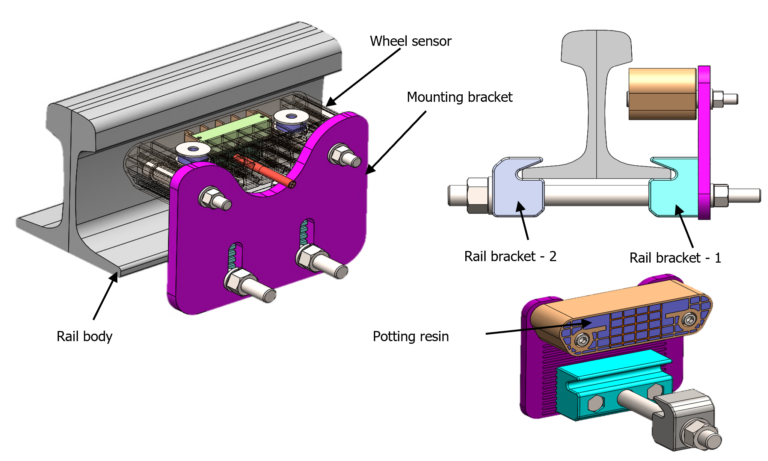 Figure.1 Rail wheel sensor assembled model
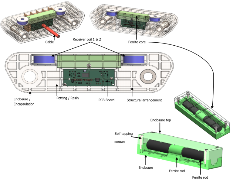
Figure 2 Rail wheel sensor system assembly
4. Material: –
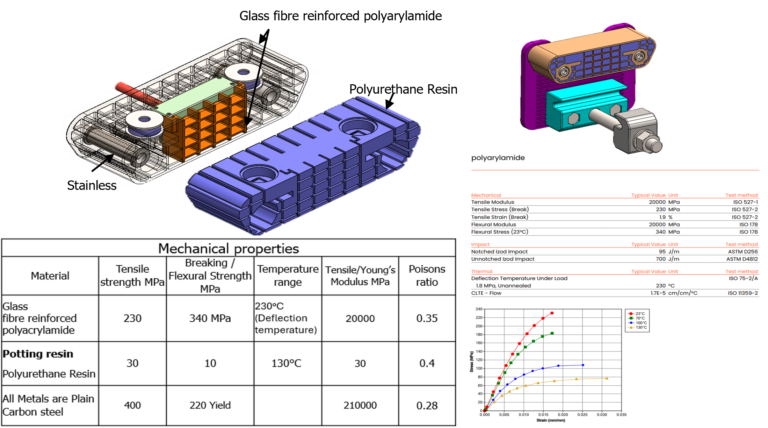
5. FE Analysis Loading case: –
- Shock load has been applied along X, Y & Z axis both positive and negative directions.
- Load magnitude of 40g at 11 milli seconds, the load to be sweep through sine curve.
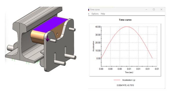
6. Mesh details: –
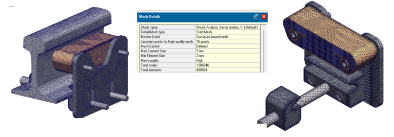
Curvature based mesh with Min. element size 2mm and Max. element size 5mm, Total no of elements is 850,924.
7. FE Analysis result: –
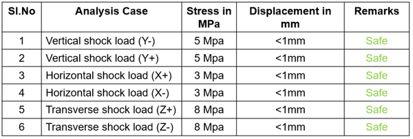
The Maximum stress at each case is observed at the metal plate and anchor bolts. The minor displacement of less than 1mm is noticed at the sensor enclosure which is well within the acceptable limit.
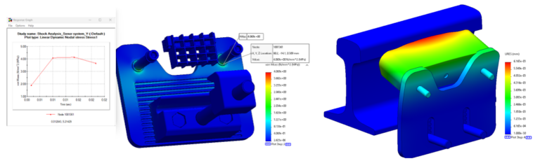
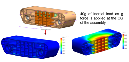
Figure 6 Analysis Stress and Displacement
The stress observed at the encapsulation is about 5.5MPa which is much lesser than the allowable limit of MOC Glass fibre reinforced polyacrylamide (230MPa). Hence, it is opined that the proposed design the material is well for the intended applications.
